Exhibition category
Contact address
| Address | 2-15-8, Minami-Shinagawa, Shinagawa-ku, Tokyo |
|---|---|
| Telephone | 81334507201 |
| URL | https://www.andor.jp/ |
| pickering@andor.jp |
Main exhibits 1
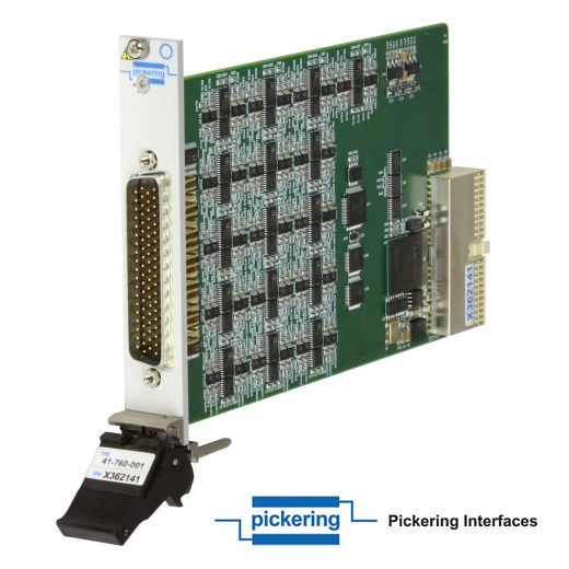
PXI Millivolt Thermocouple Simulator Module
This series of PXI Thermocouple Simulator Modules is available in a choice of 32, 24, 16 or 8 channels—each channel providing a low-voltage output across two connector pins capable of providing ±20mV with 0.7µV resolution, ±50mV with 1.7µV resolution and ±100mV with 3.3µV resolution, covering most thermocouple types.
These thermocouple simulators use two wire outputs with a remote output reference sense to ensure the modules deliver accurate low-level voltages, even if the system has common mode voltages present. In addition, each simulation channel is also able to provide an open circuit setting to simulate faulty wiring connections to a sensor.
For improved accuracy each channel of the Low-Voltage Source carries accurate calibration data stored on the module. The module also includes a calibration multiplexer for module test and verification purposes.
These are Pickering products.

Main exhibits 2
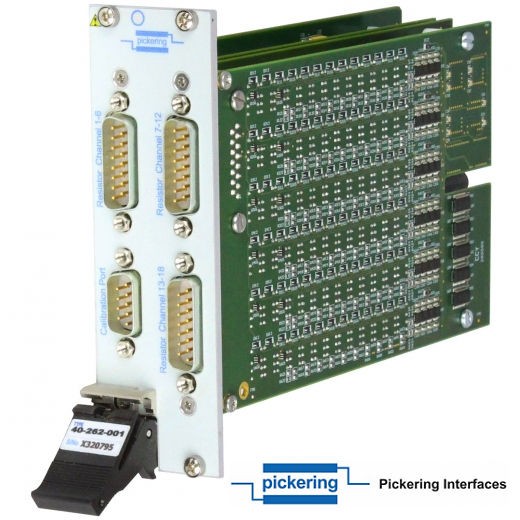
PXI RTD Simulator Module
The 40-262 is a 3U PXI module range that supports 6 (in one slot), 12 or 18 (in two slots) channels of RTD simulation. Based on the design principles of our 40-260 PXI Precision Resistor, this RTD simulator module can provide a setting resolution of <8mΩ (PT100) or <90mΩ (PT1000) and a resistance accuracy of better than 0.1% on all channels.
Each simulation channel is able to provide a short or open circuit setting to simulate faulty wiring connections to a sensor. Calibration or verification of each resistor channel can be verified by using the calibration port connected to a high performance DMM and a supplied software package.
Each module can be specified with a resistance range of either 90Ω to 250Ω suitable for PT100 simulation (40-262-001/201/101), or 900Ω to 2500Ω suitable for PT1000 simulation (40-262-002/202/102). Both resistance ranges are suitable for simulating a temperature range of approximately -25°C to 410°C for their given sensor type. The use of resistance value calls makes programming simple, an API to convert temperature requests to resistance calls using a model of the sensor being used is also available. Each channel can operate with a differential input voltage range of greater than ±15V relative to a defined common mode voltage. The common mode voltage can be set to 0V, (input range of at least ±15V), +12V (input range of -3V to +27V), -12V (input range of -27V to +3V) or an external source up to +/-50V.
These are Pickering products.

Main exhibits 3
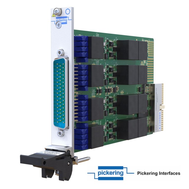
PXI/PXIe LVDT/RVDT/Resolver Simulator Module
The 41/43-670-003 is ideal for the simulation of variable differential transformers (VDT), both linear (LVDT) and rotary (RVDT) types, as well as resolvers. It has two banks, each capable of simulating the output of a single 5 or 6-wire VDT or resolver, or dual 4-wire utilizing a shared excitation signal. This allows the module to simulate up to 2 channels of 5 or 6-wire or 4 channels of 4-wire.
Each VDT bank has an independent excitation input, and the ability to use an internally generated excitation signal. The module can also take a single input and distribute to all banks, reducing the load on the source and easing cabling. Due to the use of transformers, each input and output is galvanically isolated.
The LVDT, RVDT, Resolver simulator modules are designed for a wide band of excitation frequencies, with 300Hz to 20kHz as standard, while also offering input voltages up to 38V and output voltages up to 32V. Each excitation input frequency and amplitude can also be independently read back.
The phase relationship between the input and output signals is automatically adjusted to lag one cycle, which means the phase delay can be negated. In applications where this is not acceptable, one of the outputs can be used to propagate the input signal resulting in an in-phase signal with the output, which can then be used for demodulation.
With the addition of built-in relays, the 41/43-670 can also provide short or open circuits for each channel’s inputs and outputs, reducing the need for external switching for fault insertion requirements. The programmable phase delay can also be used for simulating imperfect sensors and cabling, artificially offsetting a single or multiple outputs.
These are Pickering products.


